Monday, December 7, 2015
Flugzeugepiper Pa28 Airshampoo Aerodrome
Flugzeugepiper Pa28 Airshampoo Aerodrome

Flugzeuge De Piper Saratoga Tc Ln Aaf.
Piper Cub Logo All Vector Logo.

Flugzeuge De Piper P28 T Cockpit Map.

Piper Pa 28 236 Dakota Role Civil Utility Aircraft Manufacturer Piper.

Flugzeuge De Piper Pa28 Im Airshampoo Aerodrome.

Flugzeuge De Piper Saratoga Tc Ln Aaf.

Aerostar Aircraft History Performance And Specifications.

Flugzeuge De Piper Saratoga Tc Ln Aaf.

This Aircraft Will Not Be Finished In The Traditional Cub Yellow But.

Flugzeuge De Piper Saratoga Tc Ln Aaf Cockpit.
Read more »
Flugzeuge De Piper Saratoga Tc Ln Aaf.
Piper Cub Logo All Vector Logo.
Flugzeuge De Piper P28 T Cockpit Map.
Piper Pa 28 236 Dakota Role Civil Utility Aircraft Manufacturer Piper.
Flugzeuge De Piper Pa28 Im Airshampoo Aerodrome.
Flugzeuge De Piper Saratoga Tc Ln Aaf.
Aerostar Aircraft History Performance And Specifications.
Flugzeuge De Piper Saratoga Tc Ln Aaf.
This Aircraft Will Not Be Finished In The Traditional Cub Yellow But.
Flugzeuge De Piper Saratoga Tc Ln Aaf Cockpit.
Variable 5 to 20V DC Supply Rise
Variable 5 to 20V DC Supply Rise - In the event that you are searching for a low drop voltage controller that can give a force supply of 1A with a yield voltage of somewhere around 5V and 20V DC, National Semiconductor LM2941 Low Dropout Adjustable Regulator is that you can pick to make utilization of. Its a run of the mill dropout voltage of 0.5V which implies that the data supply require just must be 0.5V DC over the fancied yield voltage. Its different elements incorporate interior short out current breaking point and turn around battery security.
As appeared in the schematic beneath, the controller has five pins which comprises of the ON/OFF control, Input Voltage, Output Voltage, Ground and Adjustable pins. ON/OFF is utilized with the end goal of exchanging on and off of the controller. The capacitors C1 and E1 are to be set as close as possible to the controller.
The yield of the circuit can be changed by shifting the value of potentiometer VR1 from 5V DC to 20V DC. The info voltage is constrained from five.5V DC to 30V DC. Resistor R1 must be more prominent than 1K. The value of the VR1 that should be set is figured from the equation given beneath:
VR1 = R1[(Vout/1.275) - 1] ohm
On the off chance that R1=1K, Vout = 5V, VR1 ought to be set to 2.9K ohm.
On the off chance that R1=1K, Vout = 20V, VR1 ought to be set to 14.7K ohm
Structured Wiring Connecticut
Structured Wiring Connecticuit

Advanced Cabling Security Structured Wiring.

Structured Wiring Connecticut.
Structured Wiring Boom Creates Job Opportunities.

Structured Wiring Is Very Different Than The Older Way Of Doing.

Structured Wiring Connecticut.

Lifestyle Electronics Structured Wiring.

Structured Wiring Systems Installation.

Structured Wiring Panel1 Jpg.

Products Swan Structured Wiring Audio Network Ada.
Read more »
Advanced Cabling Security Structured Wiring.
Structured Wiring Connecticut.
Structured Wiring Boom Creates Job Opportunities.
Structured Wiring Is Very Different Than The Older Way Of Doing.
Structured Wiring Connecticut.
Lifestyle Electronics Structured Wiring.
Structured Wiring Systems Installation.
Structured Wiring Panel1 Jpg.
Products Swan Structured Wiring Audio Network Ada.
Drilling Floor Rear Light Rear Light Mounted
Drilling Floor Rear Light Rear Light Mounted

Basic Electrical Wiring Edward L Safford Amazon Com Books.

Da Solar Car Basic Electrical Wiring Diagram.
The Motorcycle Electrical System And Components Sound And Appear Very.

Speaking Of 3 Wire Cable Romex 12 3 Has A Black Wire For Hot A Red.
Framed Building Or Residential Home With Basic Electrical Wiring And.

Big Steps In Building Change Our Wiring To 12 Volt Dc Treehugger.

Basic Wiring For 81 Cj7.

Electrical Wiring Let S Talk Basic Residential Wiring.
Basic Electrical Outlet Wiring.

Drilling Through The Floor For The Rear Light Rear Light Mounted.
Cable Tester
Cable Tester - This link analyzer permits you to rapidly check sound links for broken wires. As a result of the low power supply voltage, batteries can be utilized which makes the circuit compact, and in this way can be utilized on area.
The outline is exceptionally straightforward and well organ-ised: utilizing the rotational switch, you select which conductor in the link to test.
 |
| Cable Tester |
The comparing LED will light up as sign of the chose conductor. This is likewise a sign that the force supply volt-age is available. On the off chance that there is a break in the link, or a free association, a second LED will light up, comparing to the chose conductor. You can likewise see instantly if there is an interior short out when other than the comparing LEDs light up too.
You can likewise test connector and splitter links as a result of the vicinity of the distinctive connectors.
Two standard AA-or AAA-batteries are adequate for the force supply. It is prescribed to utilize great, low-current sort LEDs. It is additionally a smart thought not to utilize the least expensive brand of connectors, generally there can be uncertainty as to the area of the flaw. Is it the link or the connector.
50W car audio amplifier schematic
50W car audio amplifier schematic -Car power amplifier uses SI1050GL IC as the main amplifier. The output power 50 Watt 8 ohm mono impedance. Up to 25 Volt DC voltage. with source voltage of this amplifier car battery has to work.
Minimum of 12 Volt battery voltage, less than a sound or audio is issued less than the maximum and less good. You can assemble this circuit amplifier with a schema like this.
Part List
R1 = 100K
R2 = 1R
C1 = 2.2uF
C2 = 22uF
C3 = 100uF
C4 = 0.1uF
C5 = 100uF
U1 = SI1050GL
If you want to make stereo amplifier , you must required multiply the two of components.
Read more »
 |
| 50W car audio amplifier schematic |
Part List
R1 = 100K
R2 = 1R
C1 = 2.2uF
C2 = 22uF
C3 = 100uF
C4 = 0.1uF
C5 = 100uF
U1 = SI1050GL
If you want to make stereo amplifier , you must required multiply the two of components.
Surge Protected Cheap Transformerless Hi Watt LED Driver Circuit
Surge Protected Cheap Transformerless Hi Watt LED Driver Circuit - This circuit is only a proof of idea just to demonstrate that the great old 555 clock can even now be utilized for a cutting edge and very requesting application.
 |
| Watt LED Driver Circuit |
 |
| Transformerless |
Parts list
R1 2.2 kΩ / 0.1 W
R2 10 kΩ / 0.1 W
R3 100 kΩ / 0.1 W
R4 470 Ω / 0.1 W
R5 1 kΩ / 0.1 W
R6 2 Ω / 0.25W
C1 220 pF NPO ceramic disc capacitor
C2 10 µF / 16 V electrolytic
C3, C4 470 µF / 6.3 V, low ESR
L1 custom made transformer, see text
L2 47 µH / 2 A (TDK SLF 12575 / Fastron PIS4728 series)
D1 1N4148
D2 SB240 (SB360, MBRS240, MBRD650)
D3 BZX55C 4V7, 4.7 V Zener Diode
D4 1 W High Power LED
T1 BC 337-40 (2N2222A)
T2 BC547B (2N3904)
T3 2SK2869 (IRLR2905, IRLZ 34N)
IC1 ICM7555 (TLC555, HA17555)
It is in no way, shape or form an upgraded circuit that can be promptly utilized for large scale manufacturing. It shows up generally enormous by today's standard on the grounds that I utilized just through opening segments. You may recoil it to 50 % of its unique size in the event that you utilize cutting edge SMD parts. You might likewise have the capacity to build the productivity of this circuit. Lamentably I didnt't have room schedule-wise to do broad estimations with a wide range of inductors. There may be some space for advancements.
Single Chip VHF RF Preamp
Single Chip VHF RF Preamp - Here is a high
execution RF speaker for the whole VHF telecast and PMR band
(100-175 MHz) which can be effectively assembled with no uncommon test
hardware. The grounded-entryway setup is naturally steady without
any balance if fitting PCB format systems are utilized.
The execution of the enhancer is entirely great. The commotion figure is
underneath 2 dB and the increase is more than 13 dB. The low commotion figure and great
addition will offer auto radios or some assistance with homing stereo beneficiaries get the
lower-power neighborhood or grounds radio stations, or far off novice VHF
stations in the 2-meters band. Because of the alleged limit impact, FM
beneficiaries free flags suddenly so if your most loved station blurs in
what's more, out as you drive, this enhancer can bring about a sensational change.
 |
| Single Chip VHF RF Preamp |
The MAX2633 is a low-voltage, low-clamor speaker for use from VHF to
SHF frequencies.
Working
from a solitary +2.7V to +5.5V supply, it has a for all intents and purposes level increase
reaction to 900 MHz. Its low clamor figure and low supply current makes
it perfect for RF get, support and transmit applications. The MAX2633
is one-sided inside and has a client selectable supply current, which
can be balanced by including a solitary outer resistor (here, R1). This
circuit draws just 3 mA current. Other than a solitary inclination resistor, the
just outer parts required for the MAX2630 group of RF enhancers
are info and yield blocking capacitors, C1 and C3, and a VCC sidestep
capacitor, C2. The coupling capacitors must be sufficiently huge to
contribute insignificant reactance in a 50-? framework at the least
working recurrence. Utilize the accompanying comparison to figure their
least esteem: Cc = 53000/stream [pF].
Antenna Tuning Unit ATU For 27 MHz CB Radios
Antenna Tuning Unit ATU For 27 MHz CB Radios - This reception apparatus
tuning unit (ATU) empowers half-wavelength or more wire reception apparatuses to be
coordinated to the 50-? reception apparatus data of 27-MHz Citizens' Band (CB) rigs.
The ATU is valuable in those situations where a wire recieving wire is less prominent
than a rooftop mounted "vertical" or ground-plane. It is likewise incredible for
"extemporized" reception apparatuses utilized by dynamic CB clients on campgrounds and the
like on the grounds that it permits a length of wire to be utilized as a decently
powerful recieving wire hung between, say, a tree limb at one side and a
tent post, at the other. Clearly, the wire closes then must be
confined utilizing, for instance, short lengths of nylon wire. It is even
conceivable to utilize the ATU to tune a length of security fencing to 27 MHz.
 |
| Antenna Tuning Unit ATU For 27 MHz CB Radios |
The
loop in the circuit comprises of 11 turns of silver-plated copper wire
with a distance across of around 1 mm (SWG20).
The interior breadth of
the loop is 15 mm, and it is extended to a length of around 4 cm. The
tap for the recieving wire link to the CB radio is made at around 2 turns from
the cool (ground) side. Two trimmer capacitors are accessible for tuning
the ATU.
The littler one, C1, for calibrating, and the bigger one, C2,
for coarse tuning. The trimmers are balanced with the guide of an
in-line SWR (standing-wave proportion) meter which most CB fans will
have, or ought to have the capacity to acquire on credit. Select channel 20 on the CB
apparatus and set C1 and C3 to mid-travel. Press the PTT catch and modify C2
generally advantageous (that is, most minimal) SWR perusing. Next, then again modify
C3 and C2 until you get as close as would be prudent to a 1:1 SWR perusing.
may then be changed for a surprisingly better esteem. No compelling reason to re-conform the
ATU until another radio wire is utilized. On the off chance that the length of the wire
radio wire is precisely 5.5 meters, then C3 is set to greatest capacitance.
In spite of the fact that the ATU is intended for half-wavelength or more reception apparatuses, it
may likewise be utilized for physically shorter radio wires. For instance, if
reception apparatus has a physical length of just 3 meters, then the staying 2.5
meters must be twisted on a length of PVC tubing. This makes a
purported BLC (base-stacked curl) electrically abbreviated radio wire. In
rehearse, the included curl can be made to some degree shorter than the
hypothetical quality, so the genuine length is best controlled by trial and
mistake. At long last, the ATU must be implicit an all-metal case to avert
undesirable radiation. The trimmers are than gotten to through little
gaps. The association with the CB radio is best made utilizing a SO239
('UHF') or BNC style attachment on the ATU box and a short 50-W persuade link
with coordinating fittings.
Power On Indicator
Power On Indicator - A few sorts of electronic rigging do no more give any sign that they are indeed on when they're exchanged on. This circumstance can happen when the backdrop illumination of a show is exchanged off. Also, the generally compulsory majors power pointer is currently not required with devices that eats up under 10 watts. As a result, you can just neglect to alter off such apparatus. In the event that you need to get a handle on regardless of whether rigging keeps on being drawing force from the mains, or on the off chance that you need to have a sign that the apparatus is exchanged on without expecting to switch the hardware, this circuit offers an answer.
One approach to acknowledge AC power current and create a sensibly steady voltage fair-minded of the heap is to connect a series of diodes wired backward parallel in accumulation with a portion of the AC supply leads. Here we picked diodes evaluated at 6 A that may simply handle a non-dull crest current of 200 A. The top current score is indispensable regarding switch-on streams. Favorable position of the selectedn diodes is that their voltage drop will raise at high streams (to 1.2 V at 6 A). This technique you might generally assess the vitality utilization from the brilliance of the LED (at low power degrees). The voltage over the diodes serves as the supply voltage for the LED driver. To raise the affectability of the circuit, a course circuit (voltage doubler) which joins C1, D7, D8 and C2 is utilized to twofold the voltage from D1–D6. Another advantage of this affiliation is that each split rushes of the AC present are utilized. We utilize Schottky diodes in the course circuit to minimize the voltage misfortunes.
Circuit chart :
Power On Indicator Circuit Diagram
The LED forcer is intended to work the LED in flickering mode. This expands the measure of current that could coast however the LED when it's on, so the splendor is adequate even with little hundreds. We chose an obligation cycle of pproximately 5 2ds off and zero.5 2d on. On the off chance that we expect a current of 2 mA for great shine with a low-current LED and we can endure a 1-V drop in the supply voltage, the smoothing capacitor (C2) must have a value of a thousand µF. We utilize an astable multivibrator constructed around two transistors to put into impact a high-productivity LED flasher. It is dimensioned to minimize the weight current of the transistors. The normal current utilization is around zero.5 mA with a give voltage of three V (2.7 mA when the LED is on; 0.2 mA when it is off). C4 and R4 resolve the on time of the LED (0.5 to zero.6 s, contingent upon the accessibility volt-age). The LED off time is dictated by C3 and R3 and is genuinely lower than 5 seconds. The hypothetical worth is R × C × ln2, however the genuine value runs sensibly because of the low give voltage and the selectedn segment values.
Diodes D1-D6 shouldn't need to be extraordinary high-voltage diodes; the converse volt-age is easiest a few volts right here due the opposite parallel affiliation. This voltage drop is unimportant in correlation to the value of the standards voltage. The best thing you must take now note of is the most extreme burden. Diodes with an excessiveer present rating should be utilized above 1 kW. Also, the diodes might simply require cool-ing at such unreasonable force stages. Estimations on D1–D6 demonstrate that the voltage drop all through every diode is roughly 0.4 V at a present of 1 mA. Our motivation was once to have the circuit give a moderate sign at current levels of 1 mA and excessiveer, and we succeeded viably. In any case, it's vital to make utilization of an amazing low-current LED.
Alert: the whole circuit is at AC power feasible. Never take a shot at the circuit with the primarys link connected to. The most ideal walled in area for the circuit is a little, translucent field with the indistinguishable shading as the LED. Use dependable weight helps for the primarys links getting into and leaving the crate (joined with an intersection box, for instance).
Easy to Use FM Radio Receiver
Easy to Use FM Radio Receiver - The undertaking is an easy to use and shoddy FM radio recipient which creates the sought sound signs utilizing incorporated circuit to accomplish the pre-handling units. Amid operation, the client is permitted to change stations and associate with the recipient by coordinating a keypad and a LCD for correspondence. There are a few capacities this radio collector can perform including modifying the limit when getting more grounded or weaker stations, setting up 3 most loved stations for speedy tuning, looking over/down for next solid sign station, and tuning up/down a recurrence.
Infrared Radar System
Infrared Radar System - Chris from PyroElectro.com has an awesome article around a do-it-without anyone else's help radar framework construct with PIC18F452. It's an awesome side interest task in spite of the fact that the schematic is exceptionally muddled. This task utilizes three principle gadgets to make the individual radar framework. The IR Range sensor gives yield, the pic microcontroller procedures it and afterward shows the yield on the drove cluster.
Infrared Radar Circuit Schematic
The objective of this task is to make a working ir radar framework. The framework may be required to gauge close closeness at an edge of 90 degrees as found in the illustration above. The scope of framework is about 4-30cm, 20-150cm and 1m-5.5m relying on which sensor you utilize.
Simple 50V Bench Power Supply
Simple 50V Bench Power Supply - A 50v seat power supply can be made utilizing electronic chart underneath which is composed utilizing LM10 operation amp and 2n3055 transistors. This LM10 2n3055 50v seat power supply permits a yield voltage regulation in an extent somewhere around 0 and 50 volts and the yield flow can be restricted to a most extreme of 2A. Yield voltage increments directly with the measure of resistance potentiometer P1, while the current can be balanced straight utilizing potentiometer P3. Potentiometer P2 serves to direct most extreme yield current (greatest quality is 2A).
Simple Water Level Indicator
Simple Water Level Indicator - This is the circuit graph of a straightforward erosion free water level marker for home and industries.In truth the level of any conductive non destructive fluids can be measured utilizing this circuit.The circuit depends on 5 transistor switches.Each transistor is changed on to drive the comparing LED , when its base is supplied with flow through the water through the terminal tests.
 |
| Simple Water Level Indicator |
One cathode test is (F) with 6V AC is set at the base of tank.Next tests are put regulated over the base test.
At the point when water is rising the base of every transistor gets electrical association with 6V AC through water and the comparing probe.Which thusly makes the transistors behavior to shine LED and demonstrate the level of water.The finishes of tests are joined with relating focuses in the circuit as appeared in circuit diagram.Insulated Aluminum wires with end protection evacuated will accomplish for the probe.Arrange the tests all together on a PVC channel as indicated by the profundity and inundate it in the tank.AC voltage is use to anticipate electrolysis at the probes.So this setup will last truly long.I ensure no less than a 2 years of upkeep free operation.That's what I got is as yet going.
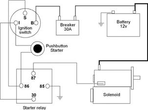
Mercury V8 Monterey 1963 Wiring Diagram Left Side Part
Mercury V8 Monterey 1963 Wiring Diagram Left Side Part - The schematic here is the wiring diagram of the 1963 Mercury V8 Monterey. The wiring diagram is divided in two different parts, here you can see the left side of the wiring diagram, and this is the Mercury V8 Monterey 1963 Wiring Diagram Right Side Part.
 |
| Mercury V8 Monterey 1963 Wiring Diagram Left Side Part |
As you can see, this wiring diagram is very clear, it shows many components and connections clearly. Some of the components you will see inside this left side part of the 1963 Mercury V8 Monterey wiring diagram are like: light switch, high beam indicator, oil pressure indicator, flasher, speedometer light, horn button, alternator indicator, etc.
Be sure to study both parts of the wiring diagrams first before attempting any wiring work like assembly or troubleshooting in your Mercury V8 Monterey. Save this wiring diagram for free in your PC.
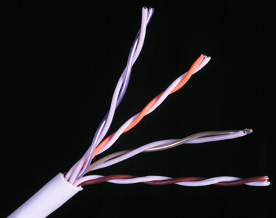
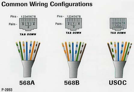
Santomieri Systemsrj45 Wire Diagrams
Santomieri Systemsrj45 Wire Diagrams - Santomieri Systemsrj45 Wire Diagrams
Wiring Power Over Ethernet Wire 500ft Roll Cat5 Cable 1000ft Roll.
Santomieri Systems Cat 5 Rj45 Wire Diagrams.

Cat5 Av Matrix Switches Cat5 Audio Video Matrix Switch Solutions.

Standard Cat 5 Wiring Schemes Learning Scholarly Technologies.
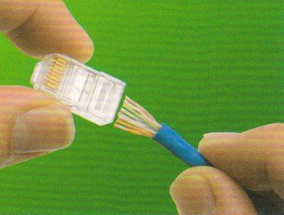
On The Crimping Tool To Permanently Attach The Rj45 To The Cat5 Cable.

The Formal Cat5 Definition Reserves The Extra 4 Wires So.

Figure 4 Wiring Diagram For An Ethernet Crossover Cable.
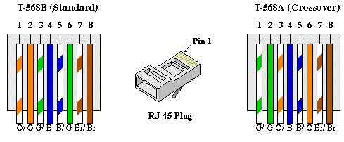
There Are Two Wiring Standards For These Cables Called T 568a And T.

Category 5 Patch Cable In T568b Wiring.

Home Phone Wiring Diagram Using Cat5 Cable Here Source Scribd Com.
Wiring Diagram Informations Thermostat Wiring
Wiring Diagram Informations Thermostat Wiring

Wiring Diagram Thr 10 Thermostat Fans Ventilation Ventilation.

Wiring And Connectors Locations Of Honda Accord Air Conditioning.

Wiring Is Generally Labeled By Color For Easy Recognition.

Always Be Aware Of The Wattage Capacity Limits Of The Thermostat.

To The Thermostat From The Left Wiring To The Roof Is Indicated On.

Honeywell Thermostat Wiring Diagram Automotive Resource The Most.
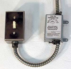
In Philadelphia 215 352 5963 Wiring Up A Thermostat To A Fan.
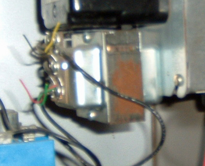
Name Thermostat Transformer Jpgviews 2348size 130 4 Kb.
Trane Heat Pump Wiring Diagram Thermostat Geotherma Heat Pumps.
Subscribe to:
Posts (Atom)